ECEN 214 Unit 2 Review
For a pdf version of this review, click here
This review is okay, it can be long winded at times, but is focused on the “why” of this unit. My goal was to give a deep understanding of the concepts, and let the math build from intuition. It was my personal favorite unit, as it is backed by some pretty neat physics concepts when we start talking about circuit elements. What an Op-Amp is can be sort of hand-wavey, but that’s because the internal circuit is too complex for our purposes, the analysis and what it does is what we focus on and care about.
Topics Covered
Textbook: Chapters 5, 6, and 7
There is a fair bit to each portion, but there are only 3 main topics covered in this unit:
- Operational Amplifiers (Op-amps)
- The component and its analysis
- Inductors and Capacitors
- The basics of the components and their behaviors
- How to combine them
- First Order Circuits
- Circuits with that can be represented with a first order differential equation
WARNING: Before starting on this unit, it’s very important you get a solid conceptual understanding of the circuit analysis techniques taught in unit 1. If you do not understand Ohms Law, KCL, KVL, Node Voltage, and Mesh Current analysis, do not start this unit. It will be much harder than it needs to be. It will take more time than it needs to. For efficiency, and to save your tears, go back and learn the first unit before starting this one. They are sequential, you can not just jump around. \newpage
Operational Amplifiers
Component Basics
Consider the component below:

Immediately, what jumps out to me, is that “Wow, this has way more connections than a resistor”, which is very true, this thing has a total of 4 inputs! Past that, however, in its function, this component is very different from the resistor, as instead of absorbing power from the circuit, it delivers a voltage. But unlike our other component that can increase potential, the voltage source, the output of this device is not a set property of the device. Instead, it produces a scaled version of its inputs, and which puts it under the category of components known as “amplifiers”. More specifically for us, however, the output here is the voltage difference of the two input terminals, whats a called a “differential input”, multiplied by (essentially) infinity, for real components its like $10^5$ or $10^6$. This large number is called the “gain” which is commonly represented by the symbol A. This specific set of qualities are given to a type of amplifier known as an “operational amplifier” or “op-amp”. There’s several parts and properties to them, but its hard to tell you about them without words, so lets define the terminals better, shall we?
- The output: The output terminal is… the output. It’s the scaled version of the inputs. Not a lot of surprises here
- The Power Supplies: +Vcc and -Vcc are the values determining the maximum and minimum values of the output.
- The Non-Inverting Input: This is the input voltage that is trying to be amplified, its essentially the “positive” voltage, and is always connected to the “+” terminal
- The Inverting Input: This is the input voltage that allows for a “difference” to be created. It gets subtracted from the non-inverting input and that value gets amplified.
Before talking about analysis, lets go over the concept of saturation. The op-amp amplifies the input voltages by an extremely large number, but it can’t actually do that to infinity. This makes sense, as if it did it would need to have infinite voltage available to it, or it would need to create energy, neither of which are possible. So, the op-amp can only operate inside of the bounds of its power supplies. Once it reaches one of those values, we call it “Saturated”. So in your analysis, if you get a value that is greater than +Vcc or less than -Vcc, cut off your value at that bound, because that is what the device is actually producing. But! When it’s inside of that non-saturated region, it’s still a linear component, since the gain is a constant, albeit very large, value, and the output is just the input scaled by the gain. This region of inputs is called the “linear region” of the device. For a bit of a picture, the graph of the output is below:
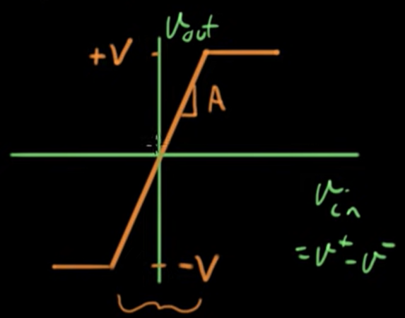
If you’re asking yourself now how we could ever get a value that isn’t just immediately saturated, since the gain is so large, we accomplish this through “feedback” circuits, where the input will get connected back to the inverting input of the device, making the differential a much smaller value.
Finally, there are just a few different common configurations of op-amps to know, but most of them are (thankfully) given self-descriptive names:
- Inverting Amplifier: Outputs amplified and negative of input because the signal is connected to the inverting input and the non-inverting input is tied to ground.
- Non-Inverting Amplifier: Outputs amplified input because the signal is connected to the non-inverting input and the inverting input is tied to ground.
- Summing Amplifier: Outputs the scaled sum of the inputs because all signals are connected to one terminal and the other is connected to ground
- Difference Amplifier: Outputs the scaled difference of the inputs because signals are connected to both terminals.
Fun little note here: those last two varieties are actually one of the foundational use cases, and a reason the component was ever designed. The word “operational” in “operational amplifier” refers to math operations because the op-amp was originally created, and still used, for math operations. With resistors we can do addition and subtraction, but in the future when we introduce components that involve derivatives, we end up being able to do more complex things like integrate functions, which is kind of neat!
Analysis with Op-Amps
If you’ve been building a conceptual understanding of the op-amp, I’m about to give you an equation that summarizes a lot of what we’ve been talking about, and I hope it isn’t too shocking (if it is though, you should probably pause and think about what the op-amp is):
\[v_o = A(v_p - v_m)\]Where:
- $v_o$ is the output voltage
- A is the gain, which is infinite for ideal components, and just very large for real ones
- $v_p$ is the voltage of the non-inverting input
- $v_m$ is the voltage of the inverting input
I call this the Op-Amp Equation, and should be the basis for your analysis, as it mathematically summarizes the operation of the component, and it makes analysis just solving for available variables. But with a little bit of arithmetic, we can write it in a different way:
\[v_o = A(v_p - v_m)\] \[\frac{v_o}{A} = v_p - v_m\] \[0 = v_p - v_m\] \[v_p = v_m\]The oddest step here is that $\frac{v_o}{A}$ goes to zero, but you have to remember that A is infinitely large relative to the inputs, so anything divided by it approaches zero. But what we’ve showed here, is that if during our analysis, we really only have to solve for the two input values and plug them into this equation, which is known as the Input Voltage Constraint of an op-amp. If you’re wondering where $v_o$ went, and how we’re supposed to find the output if the output disappears from the equation, don’t forget, op-amp’s are used in feedback circuits, so $v_m$ will always be in terms of $v_o$. You could always start your analysis from the plain op-amp equation, but this input voltage constraint just immediately does a few algebra steps that you will quickly find you do any regardless.
Now lets talk about another analysis constraint that exists, but this one is just a property of the component. A valuable use of op-amps is that they do not allow any current to pass through the components that are connected to its inputs. That means you can connect a current sensitive component such as an LED to one of the terminals, and the op-amp will read the voltage from the terminal without taking any current into it. The input terminals essentially act as voltmeters and we summarize this in the equation $I_p = I_m = 0$ and it’s known as the Input Current Constraint. Another way to say this is that there is “infinite” resistance at the input terminals. If you’re asking yourself the completely understandable question of where the supplied output voltage and current come from then, it’s from the positive and negative power supplies.
And with that you have all of the information needed to do an analysis, you can experiment on your own, or a generally pretty good process I’ve found is below:
- Write down the Input Voltage Constraint $v_p = v_m$
- Don’t forget, this is just a rewrite of the Op-Amp equation, you could start there too if you’d like
- Find $v_p$
- This one is typically easier to find because it isn’t the feedback circuit so I like to start there
- The trickiest case is a voltage source and resistor in series with the terminal, as you have to remember the resistor won’t do anything since, by the current constraint, there will be no current going through it so $v_p$ is just the voltage that the source is producing
- Find $v_m$ in terms of $v_o$
- This usually comes down to a simple case of using Node Voltage at the $v_m$ node to find it in terms of everything else
- Plug your values into the Input Voltage Constraint and solve for $v_o$ \newpage
Inductors and Capacitors
In this section, we will introduce two new, much more fundamental circuit components. They are passive components just like the resistor, but they both vary in the key idea that they can store energy. You learned about them in physics 207 (Electricity and Magnetism) and while I will use some of the concepts from that class, the final result is what’s important. Of the two, I feel the capacitor is easier to explain and understand so we’ll start there.
Capacitors
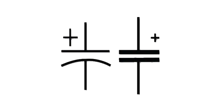
The most basic concepts of the capacitor are that they oppose a change in voltage, and they have a certain amount of Capacitance (C), measured in Farads which is a Coulomb per volt or $\frac{C}{V}$.
Capacitor Theory
Like you might have learned in 207, capacitors are two conductors separated by an insulator, such as air or some other material. The most common physical representation of this is two metal plates placed really, really, really close together, and you can kind of see this in the symbol for it.
When connected in a circuit, as current flows into the capacitor, the first plate, collects a positive charge. Since this first plate is not connected to the other one electrically, you would think no current would flow, but that would be wrong. Instead, the positive charges produce an electric field, and since the plates are so close together, the field exerts a repulsive force to the positive charges on the second plate, which creates something of an “induced current” and as these positives move away, the second plate is left with a negative charge. What’s important to remember , however, is that negative charges also create an electric field, so as time goes on, the second plate will begin to produce a stronger and stronger electric field that points in the opposite direction of the current. Eventually, the two plates will reach a point where the electric fields in them cancel each other out, pushing no additional charges, allowing no current to flow.
Capacitor Voltage and Current
We can see the theory of the capacitor mathematically, starting with the basic equation for a capacitor $Q=CV$ where Q is the charge of the capacitor, C is the capacitance, and V is the voltage across the device:
\[Q=CV\] \[\frac{dQ}{dt}=C\frac{dV}{dt}\] \[I=C\frac{dV}{dt}\]What’s vital to remember here, is that between lines 2 and 3, when I changed $\frac{dQ}{dt}$ into $I$, I didn’t do that arbitrarily or randomly, it comes from the definition of current, which is the change in charge over time. But anyway, thinking back to our concept, this equation makes a lot of intuitive sense: voltage is the potential difference generated by electric field over a distance, and initially, when you first apply the voltage there’s no push back since nothing is charged, and so the current can flow unhindered, at its maximum value but then over time, as theres more charge, and less change in the charge from moment to moment, there’s going to be less current flowing because we approach that point where the positive and negative electric fields cancel each other out. With this in mind, we can deduce that uncharged capacitors initially present to a DC circuit as a short, which they are not, and a fully charged capacitor presents to a DC circuit as an opn, which internally it is. But suppose you want to get the voltage through a capacitor, what would that formula look like? Well lets do some algebra (and a tad bit of calculus) and find out:
\[I=C\frac{dv}{dt}\] \[Idt=Cdv\] \[\int_{t_0}^{t} Idt = C\int_{V_0}^{V}(1)dv\] \[\int_{t_0}^{t} Idt = Cx|_{V_0}^{V}\] \[\int_{t_0}^{t} Idt = C(V-V_0)\] \[CV - CV_0 = \int_{t_0}^{t} Idt\] \[CV = \int_{t_0}^{t} Idt + CV_0\] \[V = \frac{1}{C}\int_{t_0}^{t} Idt + V_0\]Phew, that was a bit of work, but hopefully not too tricky. The final answer is always the most important but its always fun (to me at least) to know how we got somewhere. These two equations are important to remember, and are the current and voltage through a capacitor, but if it comes down to it, you could always derive them starting from $Q=CV$ if you got stuck. Also, just so you know, in most of your work that $V_0$ term will be zero. The only time it’s different is if the capacitor already has some amount of charge at the starting point of $t_0$.
Capacitor Power and Energy
We learned back in unit 1 that the power delivered or absorbed by a component is $P=VI$, and by the Passive Sign Convention, positive was absorption. Well that formula is generic, but still always true, and we can substitute in either our voltage or current equation to get the power of a capacitor, but since we have differentials so it can look a bit funkier than when we made these same substitutions with Ohms law. I’ll provide the two equations of the substitutions, but you’d probably be better off just substituting them in yourself rather than memorizing them:
\[P = CV\frac{dv}{dt}\] \[P = I(\frac{1}{C}\int_{t_0}^{t} Idt + V_0)\]But how do we find the energy of a capacitor? We’ll start by doing a unit analysis to come up with an approach: the energy of anything is measured in Joules (J). We have the equation for power in a capacitor, but power is measured in Joules per second ($\frac{J}{s}$). If we remember that the derivative is the rate of change of something, then we can recognize that power must be the time derivative of energy, which is something we said was true in the first unit. From this, we can derive the formula for energy in a capacitor by going backwards and solving the separable differential equation:
\[P = CV\frac{dv}{dt}\] \[Pdt = CVdv\] \[\int Pdt = C \int Vdv\] \[W = C(\frac{1}{2}V^2)\] \[W = \frac{1}{2}CV^2\]Only special thing to note, I chose to use the “W” symbol for energy, as it stands for “Work” another unit measured in Joules. This is in terms of voltage, but getting it in terms of current is way more annoying on account of the integral, so if it ever comes down to it, use this formula and substitute the formula for voltage in, but you’d pretty much always be better off getting the voltage first and then finding the energy.
Combinations of Capacitors
Capacitors are an interesting thing, that dealing with them in terms of current is tricky, the easiest way to do these derivations is in terms of charge, using the equation $Q = CV$. We’ll start with series connections. For resistors in series, their current have to be the same, as there is no nodes anywhere to add extra current in, and the same is true here, except dealing with charge this time. If we want to think of things at a smaller level, the charge on the first capacitor is what creates the push to charge the following ones, so again, the charge for all of the capacitors connected in series has to be the same. Under this idea, lets imagine we’re trying to find the equivalent capacitance of 3 capacitors and a voltage supply in series:
Using KVL we find our answer:
\[-V_s + V_1 + V_2 + V_3 = 0\] \[V_s = \frac{Q}{C_1} + \frac{Q}{C_2} + \frac{Q}{C_3}\] \[\frac{Q}{C_{eq}} = Q(\frac{1}{C_1} + \frac{1}{C_2} + \frac{1}{C_3})\] \[\frac{1}{C_{eq}} = \frac{1}{C_1} + \frac{1}{C_2} + \frac{1}{C_3}\] \[C_{eq} = \frac{1}{\frac{1}{C_1} + \frac{1}{C_2} + \frac{1}{C_3}}\]So, what we found is that the equivalent capacitance is the inverse sum of the inverses of each capacitor, which we can express as:
\[C_{eq} = (\sum_{n=1}^{\infty} \frac{1}{C_n})^{-1}\]Well then, what do we find for parallel? By the definition of parallel, all of the voltages have to be the same for every capacitor, but the current and therefore the charge is what’s different. Knowing this, we’re going to apply KCL and see what we find to a circuit with 3 capacitors a voltage source all in parallel:
\[-Q_s + Q_1 + Q_2 + Q_3 = 0\] \[Q_s = Q_1 + Q_2 + Q_3\] \[C_{eq}V_s = C_1V_s + C_2V_s + C_3V_3\] \[C_{eq} = C_1 + C_2 + C_3\]So again, we find the equivalent capacitance of capacitors in parallel is just the algebraic sum of each individual capacitance. We can express this generically as:
\[C_{eq} = \sum_{n=1}^{\infty} C_n\]If you want an easy way to remember this, you just have to notice that capacitors combine in the opposite way of resistors.
Inductors
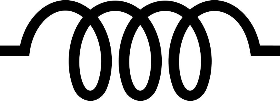
The most basic concept for an inductor is that it opposes a change in current. If you think this sounds like the opposite of a capacitor, you’d be right. Not in the physics, but all of the math for our purposes ends up supper similar. The most common physical representation of an inductor is just a coil of wire, which again (although a bit less obviously this time) you can see from the circuit symbol. Inductors are given a value known as Inductance (L), which is measured in Henrys ($\frac{V*s}{A}$). If you’re curious, inductance is represented by L to honor Heinrich Lenz, the guy who came up with the very important “Lenz’s Law” you’re about to read about
Inductor Theory
If you remember back from 207, inductors are a circle of wire (possibly of many loops) that has a current passing through it. In this class we learned about magnetic (B) fields, and how a current carrying wire would produce one, but then if you took this wire and bent it into a circle, you’d find that the produced B-field would travel all in the same direction through the loop. This passing of a magnetic field through a closed surface is called magnetic flux. Then we learned that a long long time ago the scientist Michael Faraday ran some experiments and showed that a changing magnetic flux would produce a current in the coil.
What is very interesting, however, is what Heinrich Lenz discovered by combining the two ideas into Lenz’s law. He found that the B-field creating current and the current induced by the changing magnetic field actually oppose each other! This is very cool, and is the basis for inductors and inductance, as these laws show that any sort of change in magnetic flux, such as applying a new current, will get opposed by inducing a magnetic field in the opposite direction. But! Since a changing magnetic flux induces a current the induced-opposing-magnetic field also induces an opposing current! In the beginning, because the change from no flux to… any is so great, this opposing current is pretty much equal in magnitude to what the applied current. However, as time goes on, there is less and less change in the flux, so less opposition is created, until finally the current is able to pass through unhindered, and this coil of wire is able to act like… well… a wire.
Inductor Voltage and Current
The voltage across an inductor is less immediately intuitive to me than the current formula for the capacitor, and its derivation is quite tricky so I’ll pass on doing it here:
\[V = L\frac{dI}{dt}\]The reason this formula is what it is stems from ideal wires having no resistance, as in those cases the experiments Lenz and Faraday ran actually showed that changing magnetic fields induce a voltage and not a current. Oopsy, I did a little fib, my apologies. But I did it for good reason, the importance of those two laws is that changes in current is what is important to inductors, so sue me. The formula I just gave you is actually Faraday’s Law, but without the negative sign, because this is the actual voltage, not the induced. From this though, we can kinda see that the behavior of an inductor agrees with what it is made of: Initially, when funky stuff is happening with magnets, there is actually a voltage across it but over time, as everything settles down, it behaves exactly like a wire would, not touching the voltage and allowing the current to pass through unhindered. As for the current at the beginning, it actually presents to a DC circuit as an open since by the physics, it initially gets completely opposed by that induced magnetic field, meaning no current can pass through.
The process for getting the current through an inductor is pretty well identical to the process for voltage of capacitor, so I’ll pass and just give it to you here:
\[I = \frac{1}{L}\int_{t_0}^{t} Vdt + I_0\]Inductor Power and Energy
Just like before with capacitors, since $P = VI$, you can substitute either equation in to find the power of an inductor, again I’ll give them to you, but it’s probably better to remember that relationship and do it yourself so you have one less thing to memorize:
\[P = LI\frac{dI}{dt}\] \[P = LV(\frac{1}{L}\int_{t_0}^{t} Vdt + I_0)\]Like mentioned in the capacitor section, Power is the time derivative of energy, so you can do a similar derivation to find that
\[W_L = \frac{1}{2}LI^2\]Combinations of Inductors
So, just like for capacitors, lets step through and find a formula for equivalent inductance for series and parallel circuits. Inductors are less tricky, since we don’t have to do things in terms of charges, but lets look at series first, again, we’ll use 3 inductors in series with a voltage source and apply KVL:
\[-V_s + V_1 + V_2 + V_3 = 0\] \[V_s = V_1 + V_2 + V_3\] \[L_{eq}\frac{di}{dt} = L_1\frac{di}{dt} + L_2\frac{di}{dt} + L_3\frac{di}{dt}\] \[L_{eq} = L_1 + L_2 + L_3\]So I did something funky, cancelling out the $\frac{di}{dt}$ terms, but remember, these things are in series, and so their currents are all exactly the same which means the change in current is also the same. We find then, that for in series we can express equivalent inductance as:
\[L_{eq} = \sum_{n=1}^{\infty} L_n\]Lets repeat again for parallel, knowing that components in parallel have to be the exact same voltage, which means any derivative or integral will be the same, but their currents will be different. Lets apply these ideas to a circuit with 3 inductors and a voltage source all in parallel using KCL (to make our lives easier, we’re going to assume everything is uncharged, its all gonna cancel anyway):
\[-I_s + I_1 + I_2 + I_3 = 0\] \[I_s = I_1 + I_2 + I_3\] \[\frac{1}{L_{eq}}\int_{t_0}^{t} Vdt= \frac{1}{L_1}\int_{t_0}^{t} Vdt + \frac{1}{L_2}\int_{t_0}^{t} Vdt + \frac{1}{L_3}\int_{t_0}^{t} Vdt\] \[\frac{1}{L_{eq}} = \frac{1}{L_1} + \frac{1}{L_2} + \frac{1}{L_3}\] \[L_{eq} = \frac{1}{\frac{1}{L_1} + \frac{1}{L_2} + \frac{1}{L_3}}\]How neat, with a bit of gross algebra, we again find that the equivalent inductance is the inverse of the inverse some of the individual inductances. Again, we can express this more generically as:
\[L_{eq} = (\sum_{n=1}^{\infty} \frac{1}{L_n})^{-1}\]So, for an easy way to remember this, keep in mind that inductors combine exactly like resistors. \newpage
First Order Circuits
Now that we’ve gone and defined and described our components to death, lets talk about actually putting our new inductors and capacitors into circuits with resistors. When you start making these combinations, you start creating differential equations, which shouldn’t really surprise you considering inductors and capacitors contain derivatives of the voltage or current. To keep things simple (for this unit) we’re only going to be looking at circuits that can be expressed as a first-order differential equation. To satisfy this requirement, all of our circuits will only be a combination of resistors and inductors (RL Circuits) or resistors and capacitors (RC Circuits). Additionally, all of these circuits will be of a form where either the inductor or capacitor can expressed as a single equivalent one, AND we can treat it as the load of a Thevenin or Norton circuit.
Analysis of these circuits come in two varieties:
- The Natural Response: The response of the circuit when energy stored in an inductor or capacitor is suddenly released into a resistor network
- The “Nature” of the circuit determines behavior, not sources
- The Step Response: The response of the circuit to an abrupt change in connected power, such as an increase or decrease
What will be cool to find out is that the process for analyzing them is the same, regardless of component or response type, so while I will introduce them, individually, I will wrap up in the end with a procedure for generally solving these first order circuits.
Natural RC Response
Suppose you are given the circuit below and asked to find $V_R$ for $t \geq 0^+$ assuming that it has been in the first position for a long time:
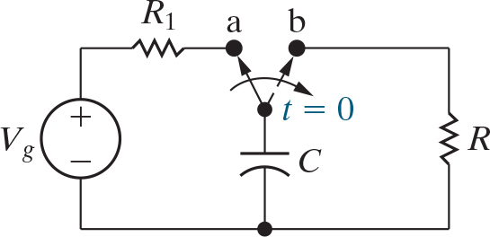
The big thing to take note of is the switch, that we treat as switching over at $t=0$ disconnecting the capacitor from the voltage source and connecting it to another resistor. So, how do we do this? Well, lets start an analysis for $t \geq 0^+$ and see what we find. Let’s try using Node Voltage Analysis (which is really just KCL in this case since there’s only one node other than the reference):
\[I_C + I_R = 0\] \[I_C = -I_R\] \[C\frac{dv}{dt} = -\frac{V_R}{R}\]From here, we’ve found a first-order differential equation, which might seem scary but luckily this one is separable, so lets solve it:
\[\frac{dv}{dt} = -\frac{V_R}{RC}\] \[dv = -\frac{V_R}{RC}dt\] \[\frac{1}{V_R}dv = -\frac{1}{RC}dt\] \[\int_{V(t_0)}^{V(t)}\frac{1}{V_R}dv = \int_{t_0}^{t} -\frac{1}{RC}dt\] \[\ln(V)|_{V(t_0)}^{V(t)} = -\frac{1}{RC}t|_{t_0}^{t}\] \[\ln(V(t)) - \ln(V(t_0)) = -\frac{1}{RC}(t-t_0)\] \[\ln(\frac{V(t)}{V(t_0)}) = -\frac{1}{RC}(t-t_0)\]Okay, we’ve done a fair bit, and we’re getting close, but we’re not quite done yet. This is the hardest part of this derivation, and in the end we’ll end up with a nice formula, but I’d somewhat know what’s going on here, when we get to second order circuits, the formulas will be… less nice. Anyway lets keep going, very quickly, lets acknowledge that for any analysis we do, we’ll treat $t_0$ as equal to 0, as it’s just a reference point and having it be zero greatly simplifies our calculations as you’re about to see:
\[\ln(\frac{V(t)}{V(0)}) = -\frac{1}{RC}t\] \[\frac{V(t)}{V(0)} = e^{-\frac{1}{RC}t}\] \[V(t) = V(0)e^{-\frac{1}{RC}t}\]Well look at that, we have found our equation for the voltage of the resistor in the circuit, how neat. Luckily for us, since everything is just two components looping, their voltages have to be the same, just opposite in magnitude by KVL, so this is not only the voltage of the resistor, it’s also the voltage of the capacitor! Very neat. But what is that $V(0)$ term? Well, as you might guess, it’s the voltage at $t=0$ which we have defined to be the moment that the capacitor switched from charging from the source to discharging into the load. But because it’s so instantaneous, the moment right before it disconnects has the same voltage as the moment after it connects, which means we can find $V(0)$ by finding the voltage across the capacitor for $t \leq 0^-$, which in this case, you can see that, pretty much by inspection $ V(0) = V_C(0^-) = V_g$ because a fully capacitor acts like an open circuit, so the resistor it was originally connected to ends up having no effect. Finding the current from the beginning would be very hard, but once we have this generic function, finding any other needed quantities isn’t terrible, lets look:
\[I(t) = \frac{V(t)}{R} = \frac{V(0)}{R}e^{-\frac{1}{RC}t}\] \[P(t) = V(t)I(t) = (V(0)e^{-\frac{1}{RC}t})(\frac{V(0)}{R}e^{-\frac{1}{RC}t}) = \frac{V(0)^2}{R}e^{-\frac{2}{RC}t}\] \[W(t) = \int P(t)dt = \int \frac{V(0)^2}{R}e^{-\frac{2}{RC}t} dt = \frac{V(0)^2}{R}(\frac{RC}{2})e^{-\frac{2}{RC}t} = \frac{1}{2}V(0)^2Ce^{-\frac{2}{RC}t}\]Overall none of these quantities are terrible to derive, I might memorize the energy equation just because it’s derivation was a tad trickier, but not by much, if you know what each of these quantities is, it shouldn’t be too hard to figure them out without memorization. What’s also important to not here is that for all of these, the quantities have the same absolute value for both, they will just have opposite magnitudes based on how you assign your polarity.
Natural RL Response
Okay, lets repeat the process again for inductors, you’re going to notice a lot of the math is very similar, so I will pass on doing the entire derivation in many cases, and if you’re curious, look back to the capacitor section, again, consider the circuit below:
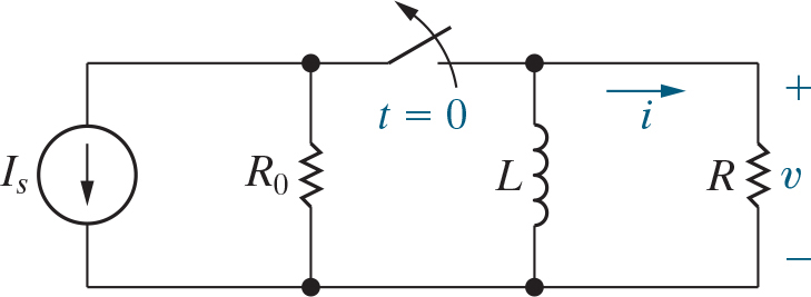
This time, if we repeat our process, doing KVL, we can find the equation $L\frac{di}{dt} + IR = 0$ after a similar derivation we can find:
\[I(t) = I(0)e^{-\frac{R}{L}t}\]where, like for the capacitor, $I(0)$ is the current across the inductor for $t=0^-$. then if you did all of your other derivations you’d get the same results for the other quantities you might want.
The time Constant
You’ll notice some great similarities between formulas for the current in an RL circuit and the voltage in an RC circuit, for your reference, I’ll give them below:
\[V_{RC}(t) = V(0)e^{-\frac{1}{RC}t}\] \[I_{RL}(t) = I(0)e^{-\frac{R}{L}t}\]What I want to take a second to look at is the exponent of e, as for both equations it’s almost identical, having a constant multiplied by your time t. Lets look at those constants a bit closer, doing a unit breakdown to find something interesting (Don’t forget C is capacitance,measured in farads):
\[\frac{1}{RC} = \frac{1}{\frac{V}{A} \frac{A*s}{V}} = \frac{1}{\frac{A*s}{A}} = \frac{1}{s}\]Okay, interesting, it turns out the quantity of $\Omega * F$ gets measured in seconds? How neat! But then looking back at the original equation, we see that the $\frac{1}{RC}$ will cancel units with t and produce $e^{-n}$ where in is just some unit-less constant!. This is very cool, and what we’ve found here is the time constant, which is measured in seconds, and RL circuits have one too:
\[\frac{R}{L} = \frac{V}{A} \div \frac{V*s}{A} = \frac{V}{A} * \frac{A}{V*s} = \frac{1}{s}\]Okay, so unfortunately, RL circuits, the formula you normally get isn’t measured in seconds. It still works since it is measured in $s^-1$ which is what we need, but to define a “time constant” in seconds, we have to invert $\frac{R}{L}$ to get in right. But hey, from here we now have two quantities in both equations measured in seconds and we can define our “time constant” as the symbol $\tau$ (tau):
RC: $\tau = RC$
RL: $\tau = \frac{L}{R}$
With this, we can recognize 2 important things about first order circuits. The first is our first explicit step towards generalization of analysis, by putting the exponent of e in terms of tau:
\[V_{RC}(t) = V(0)e^{-\frac{t}{tau}}\] \[I_{RL}(t) = I(0)e^{-\frac{t}{tau}}\]Things are starting to look real similar now aren’t they?
The other thing we can do here is think about what happens as time goes on. Since the exponent will just get reduced to a unitless constant, and the only thing in front of e is a constant, then we realize that our graph will always form a graph, and when t is integer multiples of tau then we can find out that current forms an exponentially decreasing graph:
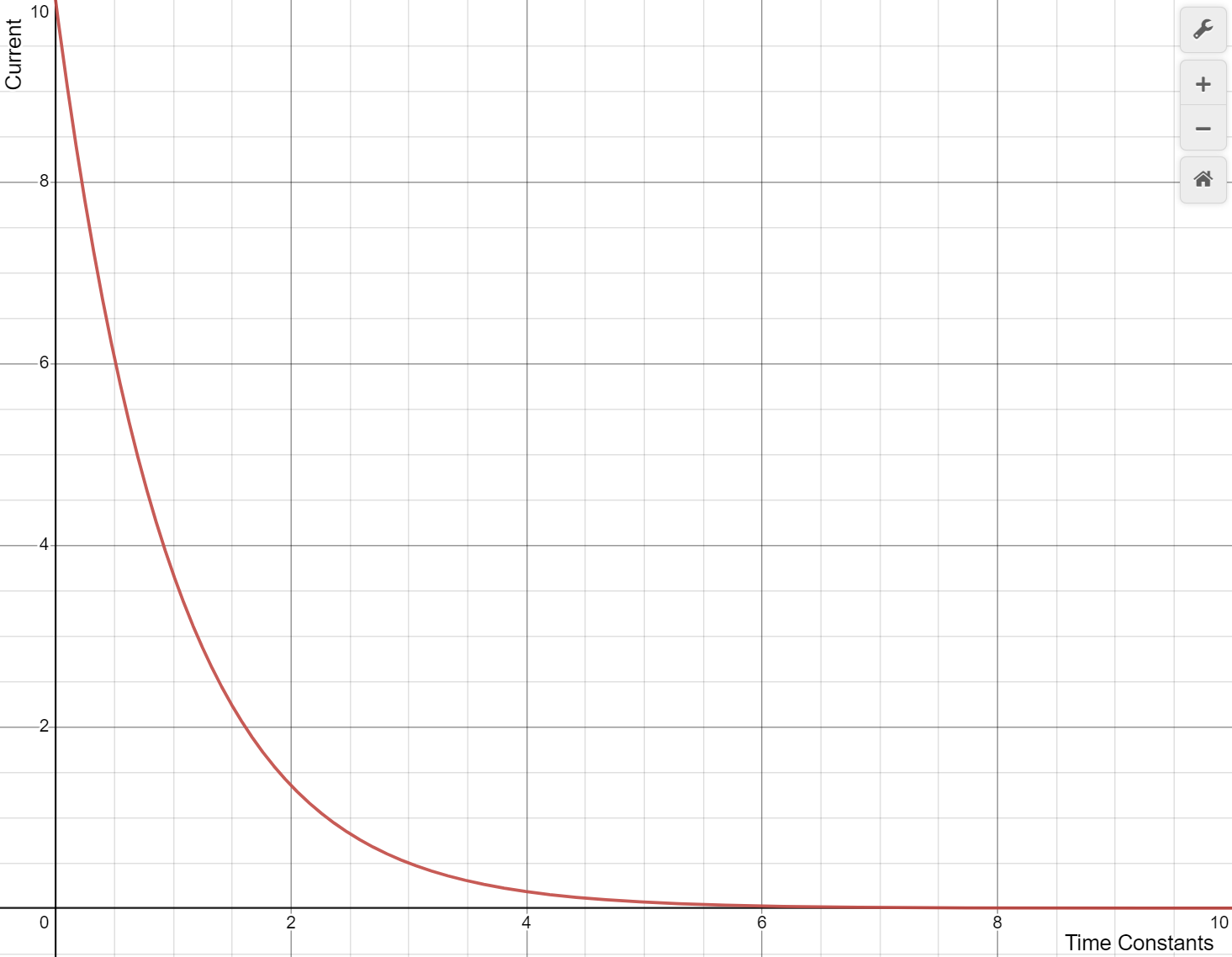
What you’ll notice is that the current gets super close to zero, but will never quite hit it. The question is though, how long is long enough? It’s standard practice that 5 time constants is defined to be the proper time to wait to consider something either fully charged or discharged.
Step Response
I will quickly go over the step response, so it’s not completely foreign, but a lot of the concepts were covered in the natural response portion, and we’re going to make a generalized approach that will remove a lot of the thought from these analyses. Consider the circuit below:
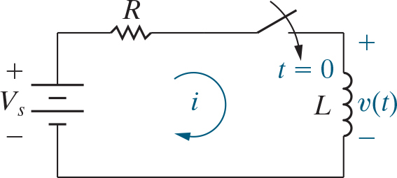
So if we look at this, when the switch gets flipped at t = 0, the inductor suddenly has a source connected to it, so lets do a KVL loop:
\[V_s = V_R + V_L\] \[V_s = \frac{i}{R} + L\frac{di}{dt}\]If we do a rather long and complex derivation that follows the same steps as finding the capacitor voltage in the natural response we can end up with the equation below:
\[I(t) = \frac{V_s}{R} + (I(0) - \frac{V_s}{R})e^{-\frac{t}{\tau}}\]If you compare it to the natural response equation, you’ll quickly notice it has almost the exact same formula, and this is something we’re going to use to come up with the generic method for analyzing first order circuits:
Steps to Analyze First Order Circuits
- Identify the variable $X(t)$ that’s easy to solve for
- In RL it’s current, in RC it’s voltage
- Calculate the initial value $X_0$ by analyzing the circuit for $t=0^-$
- Calculate the time constant $\tau$
- For RL circuits, it’s $\frac{L}{R}$ and for RC circuits it’s $RC$
- Calculate the final value $X_f$ by analyzing the circuit for X $t \rightarrow \infty$
- For natural responses, this is 0
- Plug everything into the equation $X(t) = X_f + (X_0 - X_f)e^{-\frac{t}{\tau}}$
- Solve for other quantities of interest from here
This is guaranteed to get you the correct answer every time. If it feels weird you can look and compare it to the form that the natural and step responses took, and see that equations will always end up in this form.